
Eduard 72 scale P-51D In Israeli Air Force 1948 War Markings – by Yoav Efrati
- Yoav Efrati
- Aug 2, 2025
- 9 min read
This review of Eduard's 1/72 scale new tool Mustang Royal Class dual kit combo is my recall of errors I made during the building process then is it a successful review of this kit.

The Royal Class kit offers two fuselage types, one for P-51D-5 non-fillet vertical fin Mustangs (parts tree C) and the other for fillet fitted vertical fin -5 and subsequent Mustangs dash numbers (parts tree B).

The aft fuselage difference is not apparent until step C, page 6 of the assembly process when one of two empennage-vertical fin sections is attached. Further care must be taken when choosing from the multitude of options provided in the kit which includes: two cockpit configurations, and exhaust types; three: instrument panels, canopies, propellers, vertical fins and cooling vents; along with optional fabric or metal horizontal stabilizers. 14 marking options are provided in the kit for P-51D-5 (with and without fillets), -10, -15, -20, -25 and Mk. IVa versions of the Mustang, which the 32-page chrome A4 sized instructions booklet provides clear call out information with each step. Confusion arises when the modeler wants to build a version that is not provided in the kit and can resort only to a scant number of photographs for reference. Due to the kit's inclusion of only one parts tree for a fillet fitted vertical fin (parts tree B) I had to abandon my two-fuselage simultaneous build mid-way through the kit assembly and settling for the 1949 "Operation Chorev" war of independence 101 squadron, three kill Mustang no.40 nicknamed "Tink" (short for Tinkerbell of the Peter Pan story).


The part options I used for my model are listed in the table below:
Pilot Seat Version UNKNOWN
Cockpit radios (above fuel tank) E2
Cockpit floor removal UNKNOWN
Wheel Well Color Zinc Chromate Yellow
Sub Assembly B
Sub Assembly C
Vertical Fin C14
Wing Assembly NO ROCKETS
Horizontal Stabilizer (metal) C15 + C16
Forward instrument panel E5, PE2+PE12+PE23
Combing & Gun Sight E51 + A8
Lower nose coolers (perforated) E60 + E61
Tires (Diamond) 2xR6 or 2XE41
Exhausts (shrouded) R3 & R4 or E22+E55 & E24+E67
Canopy A4
Propeller & Spinner F15 + F31
Upper Empennage Antenna E71
Building the Model:
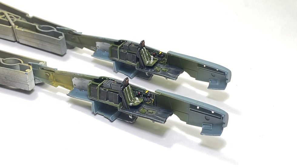
I saved time and paint by building both versions simultaneously and attached as many of the internal optional parts while the fuselage and wings were still attached to their parts trees.

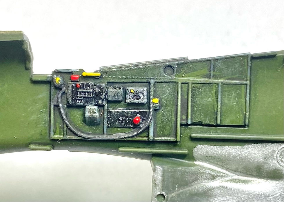
Once assembled, the wheel wells, side walls and black painted internal areas were airbrushed with ATOM-20163 semi-gloss black after which ATOM-20075 Chromate Green and ATOM-20013 Zinc Chromate Yellow were sprayed on. The black base coat imparts a shadow to corners that enhances the details. Touch up painting was done by brushing on the same colors. Raised detail and corners were enhanced by dry-brushing light grey paint. Ammoq-MiG oil paint wash mix of "Starship Filth" and black was applied to the cockpit side wall detail, wheel wells, seat, rear bulkhead and floor.

Prior to seat attachment, I added the kit provided photo etched seat belts using cyanoacrylate cement. In hindsight sight, I recommend attaching the kit’s photo etched seat belts to the seat and the seat to the rear wall, prior to painting them interior green.

The kit provides cockpit seats and radio/battery rack options for early and late production Mustangs; I used one of each option provided. Using artistic license, cockpit sidewall knobs and handles were painted white, red and yellow to make the details more noticeable.

The lower fuselage radiator assembly was attached to the left side of the fuselage and painting aluminum. Fitting the cockpit floor between the fuselage halves was a bit tricky due to the lack of rigidity of the fuselage halves. The floor was attached to the left side of the fuselage and the right side was joined to this assembly. Attention must be given to the location of the lower floor that fits above the two tabs provided on both sides of the fuselage. Cynoacrylate cement was used to achieve a strong joint without use of plastic melting cement.

The upper nose halves were held tightly together, and cyanoacrylate cement was applied from inside of the fuselage, this done to preserve the recessed panel line separating the two halves of the cowling on the exterior of the nose section.
One out of Two
Eduard 1/72 P-51D Royal Class edition provides two fuselages, a -5 (without fin fillet) and -20 (with fin fillet). I was unaware of this, until the stage where the vertical fins were to be attached.

Since IAF Mustangs were all fitted with a vertical fin leading edge fillet, I had to forgo the two kit build project and remained with the January 1949 "Operation Chorev" airframe number 40.


The lower wing section attached to the fuselage using Cyanoacrylate cement. To preserve the rivet detail, while the glue was still soft, excess cyanoacrylate cement was removed using de-bonder applied with a cotton swab. I used Tamiya Clear red, green and yellow to paint the right wing tip formation lights from the internal surface of the lower wing.

Dry fit of the right upper wing atop the lower surface revealed the need to sand the upper surface of the wheel well (marked with an X) for the upper wing skin to match the wing root fairing.

An additional problem arose when I tried fitting the upper left wing to the fuselage, I had attached the lower wing skewed to the fuselage which prevented me from attaching the upper wing surfaces! Well there goes the second model - almost - in a desperate attempt to save the model, I literally broke off the lower wing from the fuselage, my use of cyanoacrylate cement to bond the lower wing to the fuselage helped in providing a clean brake which did not damage the lower wing and fuselage. I sanded off the cyanoacrylate cement residue, and sanded down the height of the wheel wells and bonded together the upper wing surfaces only up to the gun openings.

I left the inboard sections of the upper wings free, with enabled me to cement them at the same height as the fuselage wing root fairings. The wing roots were cemented to the fuselage using Tamiya Extra Thin cement to seal the gap between them. Once the wings and fuselage were joined together, the wide gaps along the leading edges of the wings were filled with cyanoacrylate filler.

Due to slight upper and lower wing surface misalignment I had to remove the gun fairing's alignment pins from the aft surface of each part and fill gaps around the gun fairings after they had set in place. Use of fine Scotch scouring pads enabled fine sanding into compound surfaces of the wing roots and the fuselage to wing leading edge joints.

With wings in place trouble free attachment of the horizontal stabilisers finally gave the model the shape of the Mustang. Ailerons were attached flush with the wing tip in order to protect the wing tip fairing trailing edges from inadvertent breakage.


Lower fuselage intakes and radiator doors attached next and the upper nose seam excessive gap was sealed with cyanoacrylate cement and re-scribed with a razor saw for a finer scale appearance.

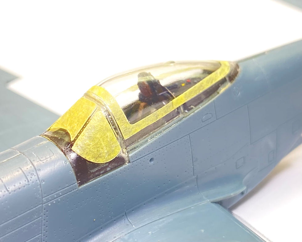
I returned to the fuselage assembly and made use of the kit’s photo etched instrument panel, painted the instrument combing AMMO by Mig Jimenez A.MIG-0032 Satin Black and cemented the windshield using clear epoxy (which does not interact with the surrounding paint and plastic).


Dry fit of the canopy shows a trouble free fit. And application of the kit provided canopy and windshield masks were found to be accurately cut, which made clear part masking a quick task.
The kit provided sponge wheel well covers fit perfectly and made masking the complex wheel well detail easy.

Prior to painting the main and tail gear, they were bored with a razor saw and .015 metal piano wire reinforcement was attached using cyanoacrylate cement which was sanded smooth after hardening.

With clear parts and wheel wells masked, the model was sprayed overall with Gunze 1500 black primer, to provide a good bonding surface for the metal paints that were to follow.
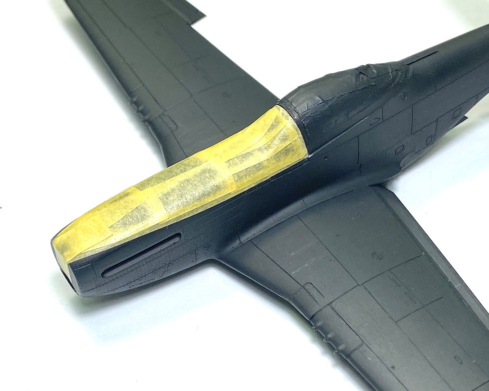
ATOM-20000 white was sprayed to form the 1948 war empennage white-blue-white band and rudder base color for the application of the diagonal red and white diagonal striped decal to follow. The width of each band is 1.5mm, the Atom-20102 blue fuselage strip was painted over the black primer followed by the Atom-20000 white bands will be masked after a day’s drying time. Gunze 1500 Black Primer did not allow for AMMO Mig Jimenez ATOM paints to bond to the surface (or Tamiya acrylic paints for that matter). Which required repainting using enamel and lacquer based paints to be used. Areas where paint was removed – using pharmaceutical alcohol were resprayed with Gunze 1500 black primer.

The rudder, spinner and empennage identification band were repainted using Revell white 301, red 330, blue 351; followed by Humbrol 11 silver wings; AK 480 Dark Aluminum lower center wing and exhaust panels; Alclad ALC-106 White Aluminum fuselage, empennage and control surfaces. The cellulous based paint was left to cure for 24 hours, prior to a spray application of acrylic based Future Klear diluted with pharmaceutical alcohol for rapid drying.


Markings for depicting the 1949 vintage "Chorev Operation" Mustang number 40 were sourced from IsraDecal sheet IAF-7 Israeli AF P-51D Mustang and Sky"s Decal sheet number 21/22 "IAF First Fighters". Touched up brush painting of the red decal areas using ATOM-20028 which matched the red used in the decal graphics.


AMMO-MIG washes were used for panel line enhancement and AMMO-MIG "Starship Filth" oil paint was used to simulate oil streaks. Final assembly included installation of the main landing gear wheel well taxi light followed by the main gear. Main gear door attachment has locating pins for a positive fit, but first make sure that the oleo scissors face aft. When installing the tail gear, make sure to insert the strut into the aft hole in the wheel well. A pair of 100 lbs bombs provided in the kit were brush painted AMMO-MiG Olive Drab and attached to the lower wing pylons.
Conclusion: Eduard's new tooled P-51D Mustang kits provide modelers the most accurate and highly detailed 1/72 scale model kit produced to date. Ample external stores and variant options require the modeler to study the aircraft they intend to depict prior to building the model. Prior to diverging to a version of the Mustang not provided in the ample number of decals options provided in the kit, I highly recommend building a model or two straight out of the box in order to become familiar with the multiple versions possible with each kit.
Photos of completed model:
Note: double click the images below to view the full size image.


If you like this article and want to support my efforts in maintaining this web site you may make a donation through my PayPal account yoave@elal.co.il
Thank you,
Yoav Efrati


Comments